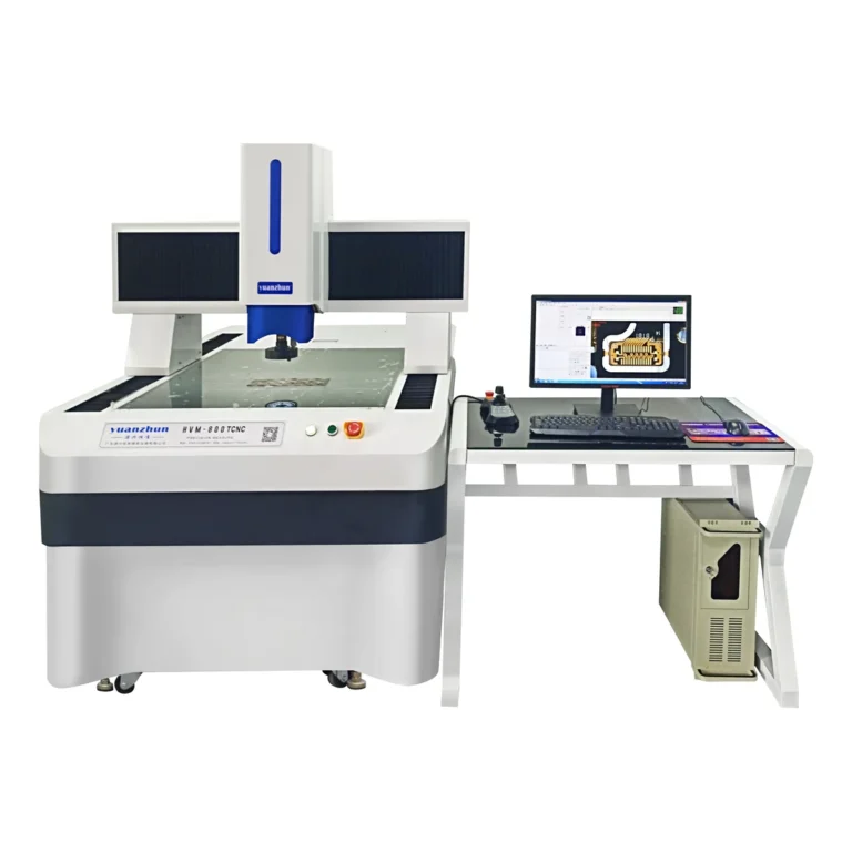
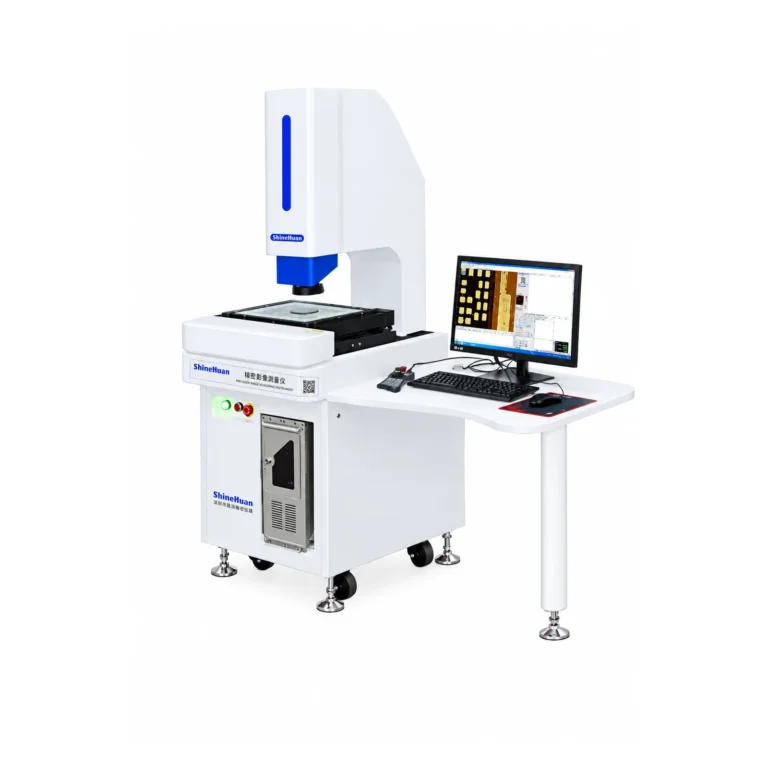
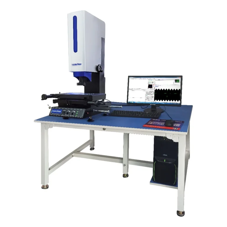
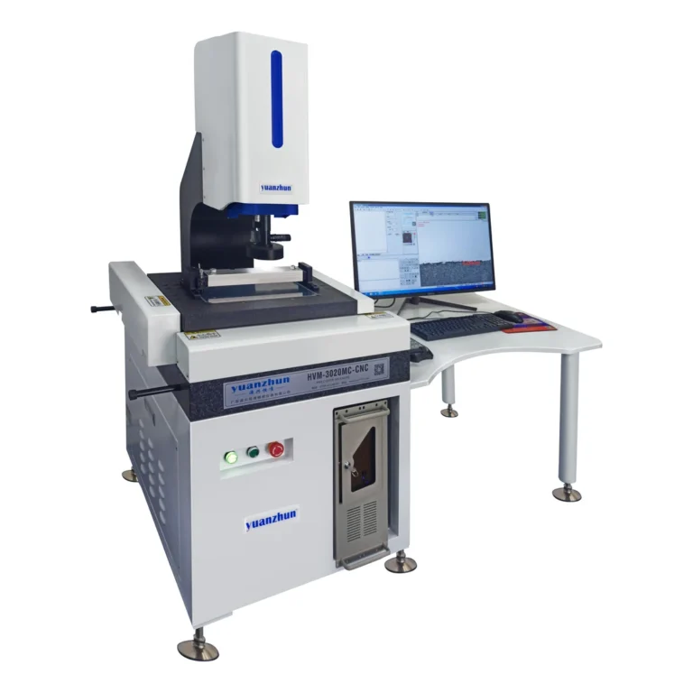
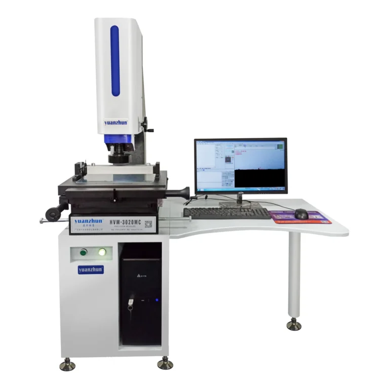
Automated measurement systems can reduce repetitive operator steps and make inspection routines more consistent, but automation does not remove the need for a sound measurement method. The best starting point is a representative part, a clearly defined tolerance requirement and a baseline for the current manual process. This guide explains how to evaluate a move from manual inspection to CNC measurement without assuming that every part needs full automation.
What is an automated measurement system?
In dimensional inspection, an automated system uses a programmed sequence to position, acquire and evaluate features, then record results. Depending on the application, this may involve CNC stage movement, optical imaging, probing, software measurement routines or a combination of methods. Loading, fixturing, program selection and reviewing exceptions may still require an operator. The configuration should match the features, materials, tolerances and production flow, not just a desired level of automation.
Start with the real inspection bottleneck
Map one complete manual inspection cycle, from retrieving the part to approving the report. Separate time spent on loading, alignment, measuring, data entry, review and program changeover. Note the number of part variants and the inspection frequency. If most time is spent waiting for parts or interpreting ambiguous specifications, a faster measuring routine alone may not solve the problem.
Define a baseline for cycle time, operator involvement, remeasurement rate and report completeness. When comparing alternatives, measure the same complete cycle rather than only the machine’s motion or image-acquisition time.
Match the measurement method to the part
- Features and tolerances: list critical dimensions, datums, measurement range and required uncertainty or acceptance limits.
- Surface and geometry: test reflective, transparent, dark or irregular features under realistic lighting and presentation conditions.
- Access: confirm whether each feature is visible to an optical system or needs another sensing method.
- Part variation: include worst-case samples, not only an ideal part, when proving the routine.
For a comparison of suitable methods, see vision measuring versus CMM. Do not infer measurement capability from repeatability alone: the proposed method also needs to meet the specified accuracy and uncertainty needs. NIST describes measurement-system characterization in terms of reference comparisons, operating conditions, resolution and repeatability.
Design fixtures and programs for repeatable setup
Reliable automation begins with consistent part presentation. A fixture should locate the part without distortion, expose the required features and permit safe loading and unloading. Document datum selection, orientation, clamping and cleaning. If the part can be loaded in more than one plausible position, test how the routine detects or prevents an incorrect setup.
For a CNC video measuring system, validate focus, illumination, edge detection and measurement sequence on representative parts. Check program permissions, version control and how operators select the correct routine. A program that works on a clean sample may need revision when normal variation or residue changes the image.
Specify the data and quality workflow
Before selecting software, specify the required result fields: part and lot identification, measured values, tolerances, pass/fail rules, operator, instrument, time and program revision. Decide where reports are stored, who reviews exceptions and whether the system must exchange data with other tools. Confirm the chosen model’s actual export and integration options rather than assuming every automated measurement system supports the same interfaces.
Run a pilot with measurable acceptance criteria
- Select test parts: include normal production variation, critical dimensions and realistic surfaces.
- Agree on references: define the accepted method or reference artefacts, environmental conditions and pass criteria before testing.
- Repeat the study: include multiple loads and, where relevant, operators or shifts to expose setup effects.
- Time the full cycle: include loading, changeover, measurement, report review and any rework.
- Review exceptions: assess false rejects, missed features, data completeness and recovery after an interrupted run.
Keep the pilot results with the approved program and fixture configuration. If results miss the criteria, resolve the underlying setup or method before scaling to production. A measurement-system study should be proportionate to the decision being made and the applicable quality requirements.
Plan training, maintenance and support
Operators need a clear routine for loading parts, choosing programs, checking references and handling failed checks. Assign responsibility for program changes, calibration, backups and periodic verification. Our precision measuring instrument maintenance guide covers daily care and what to do when verification fails.
Next step: evaluate your application
Bring a representative drawing, parts, expected volume, tolerances and reporting requirements to a supplier discussion. Ask for a demonstration using your actual inspection task and agree on the configuration, acceptance test, training and service scope. Explore the Enhanced HVM ZCNC video measuring machine, or contact Ideal Precision to discuss whether an automated measurement approach fits your parts.
Evaluate the software workflow
Once the measurement method and fixture are defined, use this image measurement software checklist to validate edge detection, programs and reports on sample parts.