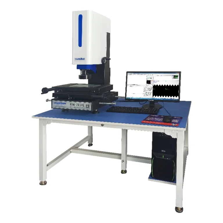
PCB and FPC dimensional measurement begins with a defined feature on the drawing. An outline, hole location or pad position needs a clear reference and a repeatable setup. This guide explains what to prepare before evaluating a vision measuring routine; it does not treat electrical testing or general defect inspection as the same task.
1. Separate the required checks
Make a feature list from the current drawing revision. Record the dimension, tolerance, datum and reporting requirement for each item. Distinguish an outside profile from a hole location, and distinguish a visible pad boundary from a feature that cannot be reached optically.
Mark uncertain edges on an annotated image. If the drawing and the visible boundary do not obviously describe the same characteristic, resolve that definition before comparing results. A repeatable measurement of the wrong edge is still the wrong measurement.
2. Define how the sample is supported
For a rigid panel, review fixture clearance, support points and loading orientation. Confirm that the whole measurement routine stays within the usable envelope with the fixture in place.
For a flexible circuit, specify whether the requirement applies in a free state or under an agreed support condition. Avoid stretching or flattening it differently each time. Record the fixture and the positioning sequence so a second operator can reproduce the setup.
3. Evaluate illumination on real surfaces
Include representative solder-mask colours, reflective surfaces and edge conditions in the trial. Review lighting and focus for the required feature rather than choosing settings from the easiest-looking sample. Save the agreed settings with the routine where supported.
A clear image is useful, but the trial must also establish how the software identifies the edge and calculates the reported feature. Review the measurement software checklist when discussing these functions.
4. Test repeat inspection after reloading
Measure a sample, remove it, reload it and repeat the routine. Review the influence of alignment and support as well as instrument motion. Include realistic part variation and discuss how an unclear edge or failed alignment should be handled.
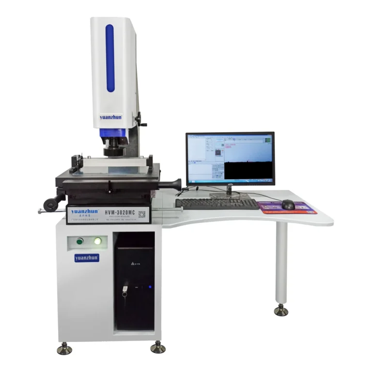
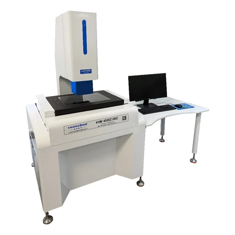
When comparing manual and CNC workflows, time the complete process: loading, locating, measuring, reviewing and reporting. The movement portion alone is not the production cycle. Larger panels may also require a review of travel, fixture clearance and operator access.
5. Prepare the application brief
- Drawing revision, datums, critical dimensions and tolerances.
- Board or circuit size, material, finish and support condition.
- Representative samples or images, including difficult features.
- Expected part mix, inspection volume and report fields.
- Any required interfaces or special loading arrangements.
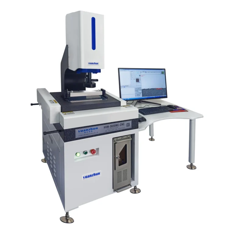
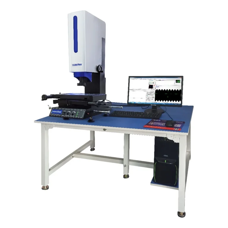
Use the PCB and FPC application page to compare equipment routes. For repeated optical routines, review the CNC vision measuring range. Submit the brief through an application inquiry so the selected configuration can be assessed against the actual task.