Cutting, slitting and tab forming can leave burrs on battery electrode edges. A burr’s visibility depends on its direction and how the edge is presented to the optics. A useful battery electrode burr inspection process therefore starts with a defined feature and an agreed acceptance rule—not a magnification setting alone.
This guide outlines a practical optical workflow for cut electrodes and tabs. It is a measurement-planning guide, not a universal burr-height limit or a substitute for your cell-design and safety validation.
Why inspect the cut edge?
Electrode slitting and cutting can create projections at the foil edge. Their orientation matters: an edge viewed from above may reveal a lateral projection while concealing one that points out of the foil plane. Industry application guidance distinguishes horizontal and vertical burrs and notes that protruding edges can interfere with downstream assembly or damage a separator. The inspection plan should identify which edge condition is relevant to the drawing and process.
Define the measurand before choosing equipment
- Part and location: Record the electrode or tab type, material, cut edge, and the positions to sample.
- Feature and direction: Specify whether the result is a visible lateral projection, a vertical protrusion, edge irregularity, or another drawing-defined dimension.
- Datum and limit: State the reference edge, units, tolerance, and decision rule. Do not borrow a generic limit from another battery design.
- Evidence: Decide whether the report needs a scaled image, measured value, location, part or lot ID, and pass/fail result.
A top-view 2D outline can help quantify a visible projection, but it does not automatically establish the height of a burr rising out of the foil plane. If height is the acceptance criterion, verify that the viewing geometry and measurement method can resolve it on representative samples.
A repeatable optical inspection workflow
1. Select representative samples
Include edges from normal production and samples near the proposed acceptance limit. Record the cutting or slitting process, sample orientation, and location so results can be traced back to the operation being evaluated.
2. Present the edge without changing it
Support thin foil or tabs without flattening the feature under inspection. Keep the target edge exposed and use the same fixture position and viewing direction for every comparison. Document any repositioning needed to observe another side of the edge.
3. Set optics, lighting and scale
Choose illumination that separates the burr from the parent edge without washing out the outline. Check focus at the feature, confirm the measurement scale using an appropriate reference, and save the lighting and magnification settings. Test the setup on the smallest feature you must reliably resolve; a larger displayed image alone is not proof of measurement capability.
4. Measure and review ambiguous edges
Measure the drawing-defined dimension from the specified datum at the required locations. Keep tears, loose particles and coating artifacts distinct from a burr measurement. If a feature cannot be separated confidently from the background, flag it for a second view or a suitable complementary method rather than forcing a numeric result.
5. Record results consistently
Save the measured value and units together with an image, location, sample ID, setup or program revision, and the applicable tolerance. Review repeatability with multiple operators or repeated setups before using the result as a production decision point.
Manual or CNC burr measurement?
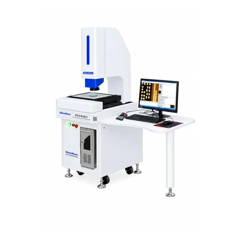
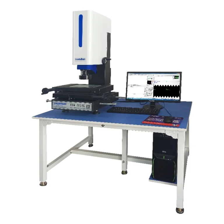
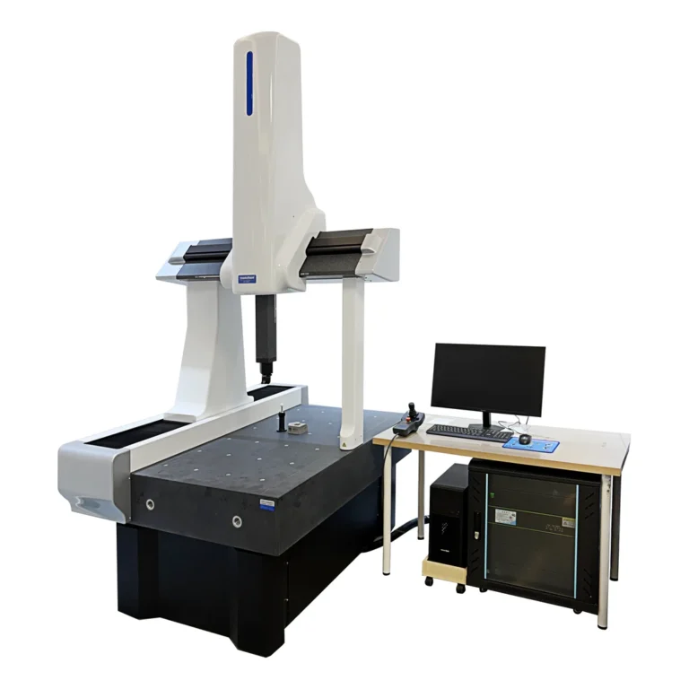
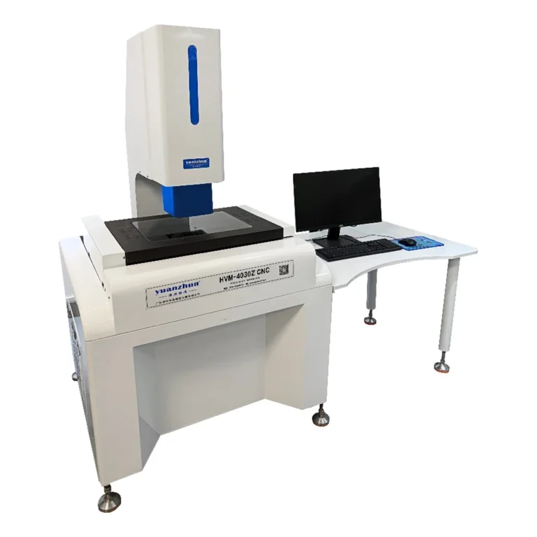
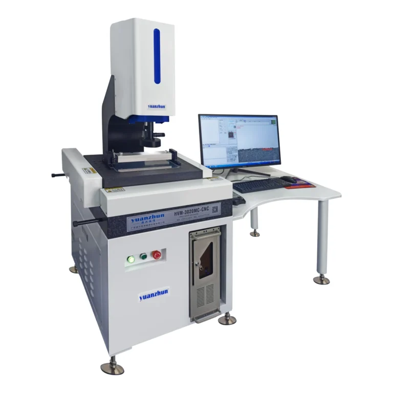
A manual burr measuring instrument can suit changing part geometries, method development, and smaller batches where an operator needs to review each edge. A CNC burr measuring instrument may help repeat the same inspection routine across consistent fixtures and parts. Compare the full loading, positioning, measurement and reporting cycle—not just the measurement step. Confirm the selected model’s field of view, fixture, software functions and reporting format against your samples and quotation.
Questions to settle before requesting a measurement trial
- Which electrode or tab edge, process step, and burr direction are in scope?
- What dimension and reference datum are specified on the drawing?
- What are the sample dimensions, expected feature size and acceptance limit?
- How many locations and parts must be inspected per batch?
- What images, measurements and traceability fields must the report contain?
Send your drawing, representative parts and reporting requirements to Ideal Precision’s team to discuss an appropriate optical inspection setup. We can review a proposed method against your samples; final acceptance criteria and validation remain specific to your process.