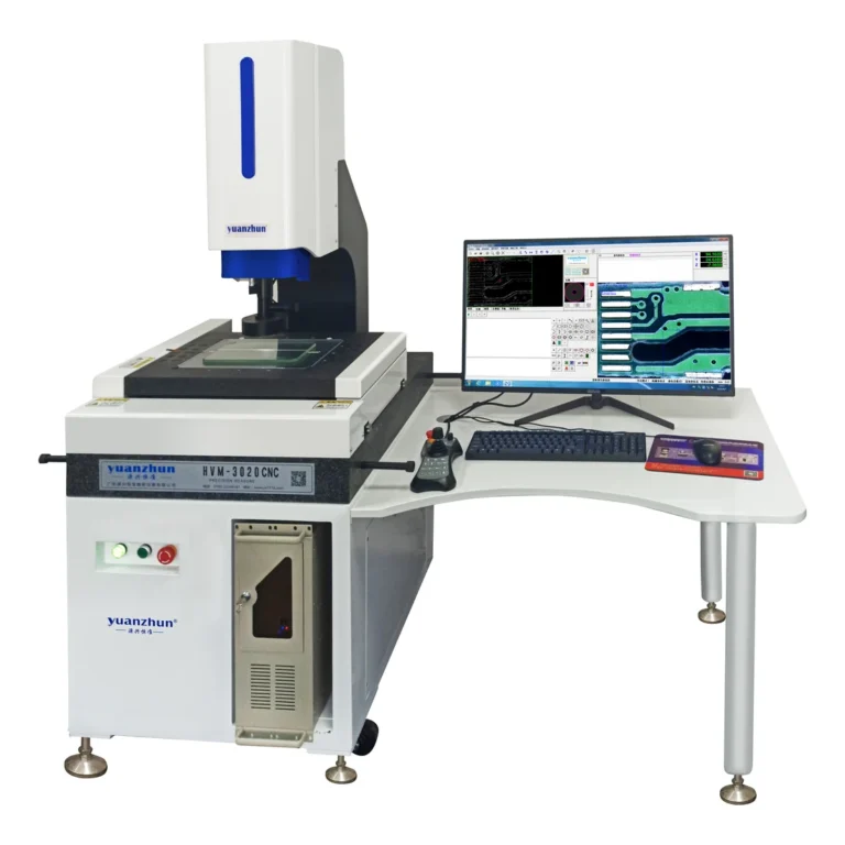
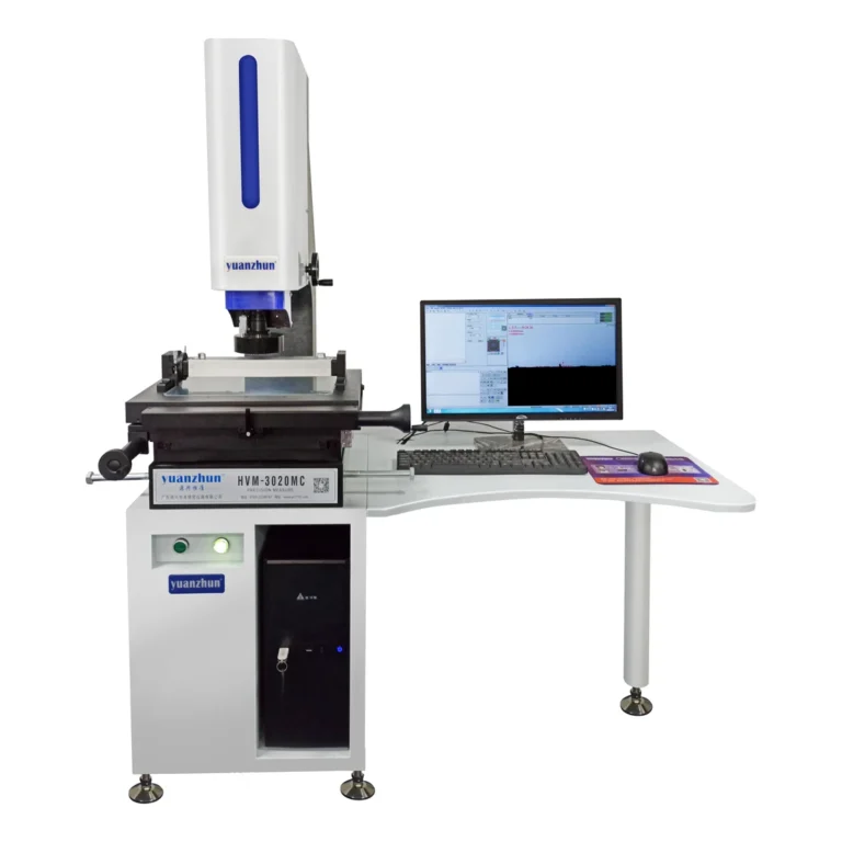
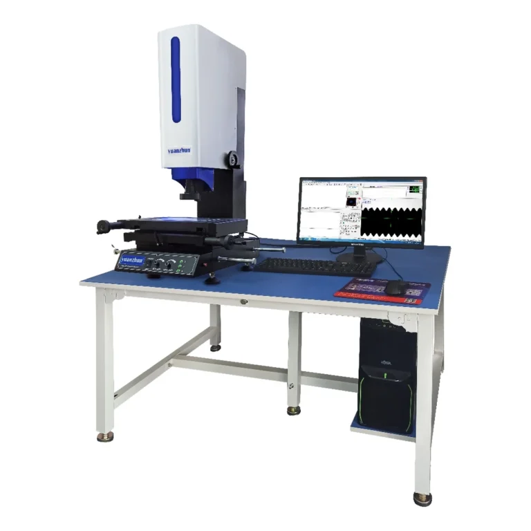
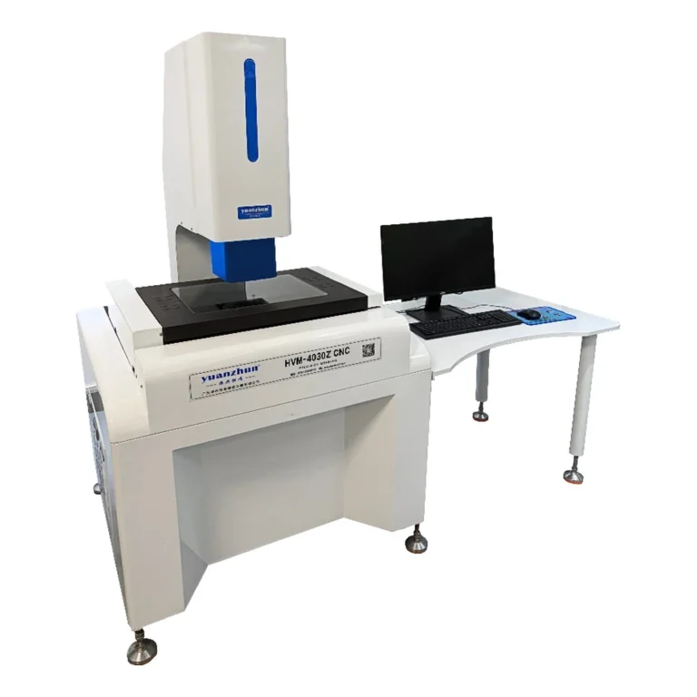
An automotive housing drawing can combine visible outlines, hole positions, surfaces and datum relationships. One measurement method may not suit every characteristic. A useful inspection plan identifies which features can be seen, which can be reached and what result the drawing actually requires.
Build a feature and datum list
Start with the current drawing revision. Record each critical characteristic, its tolerance, reference datums and reporting requirement. Include the material, surface finish and any sample condition specified for inspection.
Separate the visible boundary of a hole from the characteristics of its interior. Similarly, a projected outside profile does not automatically establish the geometry of the full surface. These distinctions determine which methods deserve evaluation.
Review optical visibility
A vision measuring system can be evaluated for suitable visible edges, outlines and positions. Check orientation, illumination, focus and the way software defines the edge. Reflective or irregular finishes should be represented in the sample trial.
For a feature that is more accessible from the side, review the fixture and a suitable viewing arrangement. Do not assume that a different camera angle alone resolves every access or tolerance requirement.
Review tactile access and part support
A coordinate measuring machine can be evaluated for accessible three-dimensional features and datum relationships. The probe or stylus must reach the required surface, and the fixture must support the part appropriately for the method.
Review clearance, part rigidity and the intended measurement sequence with the configuration. The vision measuring machine versus CMM guide provides a broader comparison of the two approaches.
Validate the combined inspection plan
Use representative parts, including realistic surface conditions and variation. Repeat the routine after reloading and review how the datum alignment is established. Where multiple methods are used, document which method owns each characteristic and how records are associated with the same part.
Agree how results are checked against the tolerance, how uncertain features are escalated and which conditions must remain controlled. Equipment selection should support the inspection process; it does not replace the organisation’s quality system or establish an audit outcome.
Prepare a useful inquiry
Send the drawing, marked features, tolerances, material, finish, sample dimensions and inspection volume. Include any existing fixture and report format. If certain surfaces cannot be reached or seen, identify them explicitly.
For the equipment discussion, start with automotive dimensional inspection applications. Review the YZ Series CMM and relevant CNC vision systems against the method requirements. Confirm the selected configuration through an application review.