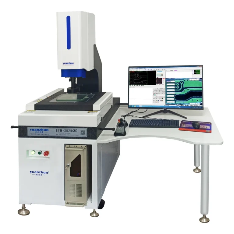
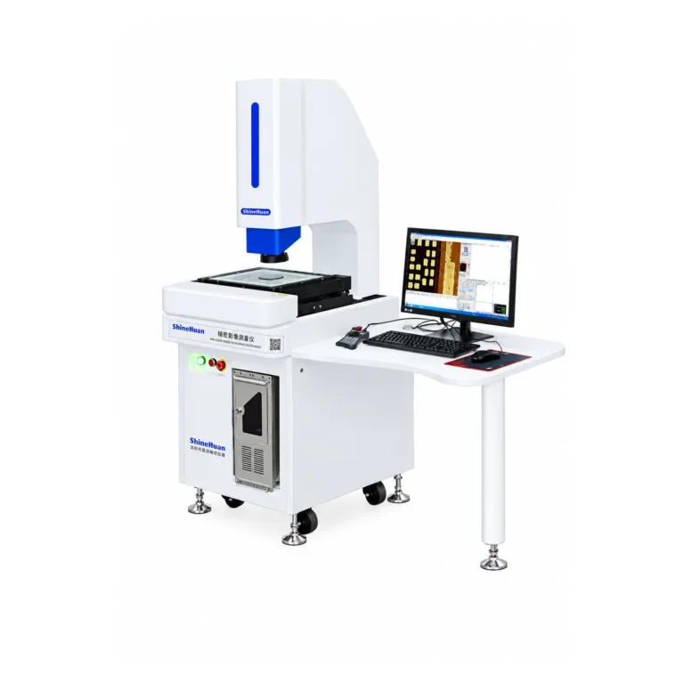
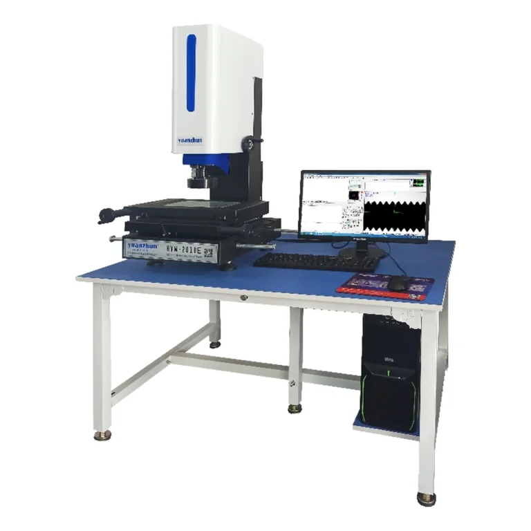
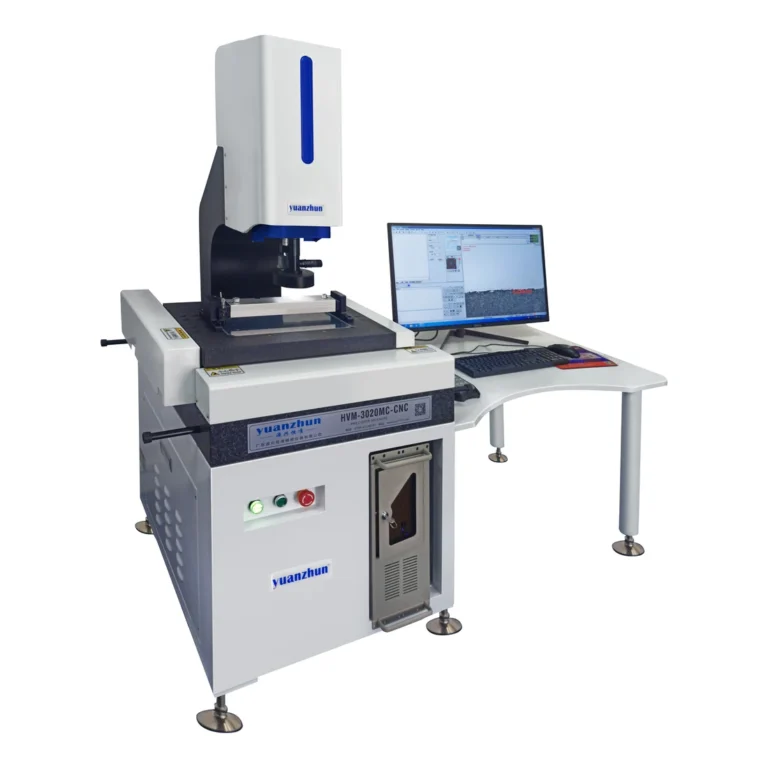
Quick answer: A 2D video measuring machine is a natural fit for features measured in the image plane, such as visible distances, hole positions and profiles. A 2.5D configuration adds height-related measurement functions, but its capability depends on the optical method, software, travel and part surface. It is not a substitute for every tactile 3D measurement.
Start with the drawing’s features
Separate the characteristics into two groups. First, mark dimensions defined by visible X/Y edges or centers. Then mark heights, steps, flatness or features on different planes. Ask how each height is established, which surface is the reference and whether the proposed optical method can resolve that surface reliably. Transparent, highly reflective or steeply sloped areas may need a different setup or method.
When 2D is enough
For flat stamped, machined or electronic parts with clearly visible planar edges, a 2D workflow may be simpler to set up and validate. The important questions are still field of view, measuring travel, edge contrast, fixture repeatability and the required tolerance. Explore the manual video measuring machine series when the operator can position and measure each part.
What 2.5D adds—and what to confirm
A 2.5D system can combine image-plane measurements with specified height or flatness functions. The local HVM E manual 2.5D series lists image-based height and flatness measurement functions; confirm the final software, Z travel and measurement method for the model offered. Do not infer a universal depth range or accuracy from the term “2.5D.”
- Feature: Can the lens and lighting distinguish the surface and reference plane?
- Method: Is the height result derived from a suitable focus or other validated routine?
- Access: Can the stage and Z axis reach every area without collisions?
- Evidence: Does the report show the datum, method and units required by your quality plan?
Run a sample-part study
- Send the drawing with tolerances and note every height-related characteristic.
- Measure representative parts across the expected surface and finish variation.
- Repeat the setup and compare readings with an appropriate reference method.
- Review uncertainty and repeatability against the tolerance before accepting the process.
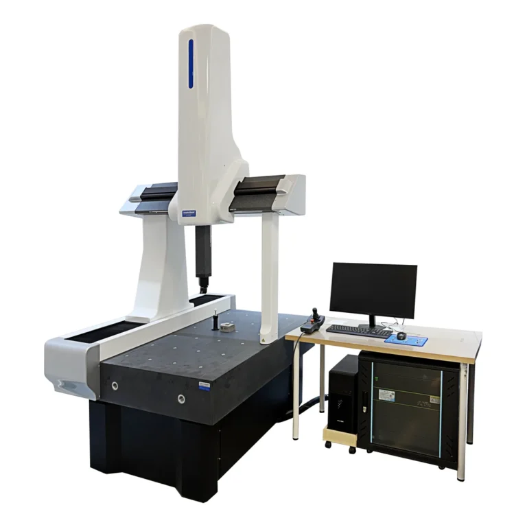
For hidden 3D geometry or features a camera cannot observe, compare a probing solution using our vision versus CMM selection guide. A sample-based application discussion is the best way to decide which model and method are appropriate.
For a part-based example, see the precision hardware measurement guide covering stamped components, shafts and machined housings.