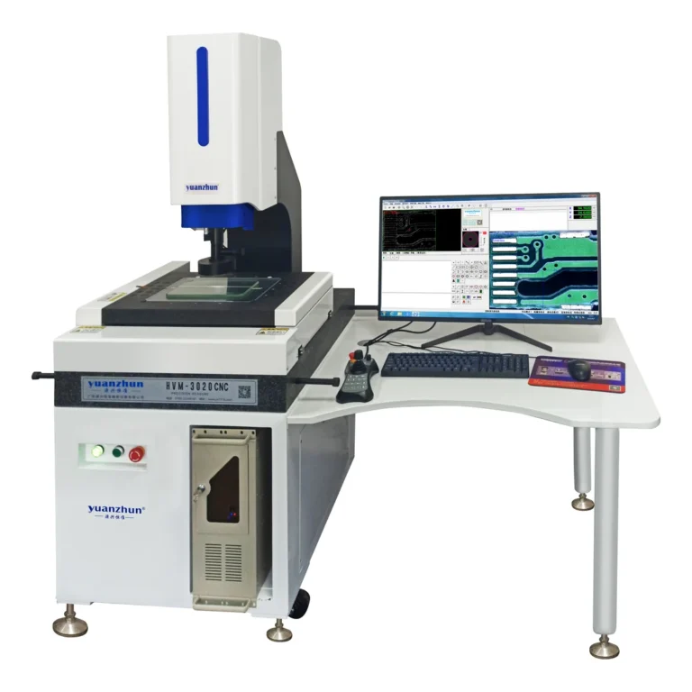
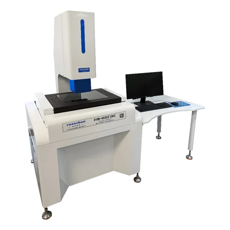
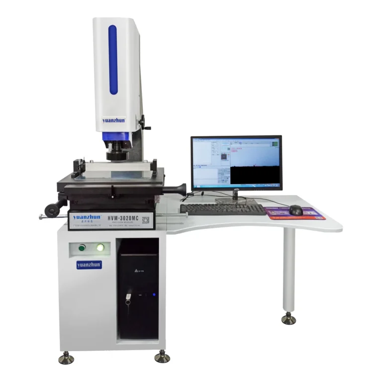
When inspecting a stamped part, a visible outline may include a burr, chamfer or reflection as well as the intended profile. Before selecting a measuring routine, agree which boundary represents the characteristic on the drawing. This definition connects the image to the acceptance decision.
Identify the characteristic, not just the silhouette
Mark the feature, dimension, datum and tolerance on the drawing. Explain whether the task concerns a nominal contour, hole size, distance, angle or a defined edge defect. Do not substitute an easily visible boundary for the required one without checking the method.
For a burr inspection, define the viewing direction and the characteristic to report separately from the normal part dimensions. A single top-view outline should not be assumed to describe every aspect of an edge.
Include realistic edge conditions in the trial
Provide representative parts with normal variation in finish and edge condition. Where available, include examples that are difficult to interpret and samples close to the acceptance limit. Describe why each sample was selected so the trial can address actual production concerns.
Review illumination and focus on the required feature. If changing the lighting causes the apparent boundary to move, document the settings and investigate how that influences the result. Do not choose the setting simply because it gives a preferred number.
Control fixture contact and orientation
Support the part so the fixture does not change the characteristic being inspected. Record the loading direction, contact points and datum alignment. Thin or easily deformed pieces need a consistent support condition.
A side-view arrangement may deserve evaluation where the required profile is difficult to inspect from above. The HVM W horizontal system provides a different viewing arrangement, but its suitability still depends on the actual part and feature.
Check the routine after removing the part
Repeat the measurement after unloading and reloading. Include the operator tasks and alignment steps when assessing repeatability. If the routine uses automatic edge detection, check how it responds to realistic changes in the sample rather than testing only a single ideal image.
Compare with a suitable reference method where appropriate and agree how uncertain or inaccessible features will be handled. Record the routine, lighting, fixture and program version alongside the report so the result can be interpreted later.
Choose the equipment route from the evidence
Manual vision instruments, CNC systems, flash measurement and dedicated burr instruments serve different workflows. Compare the complete loading-to-reporting process, feature access and required result before choosing.
The precision hardware measurement guide explains method selection across different feature types. Use mold and hardware applications for the equipment discussion, and send your drawing and edge examples through an application review request. Confirm the selected model specification and agreed measurement conditions before ordering.