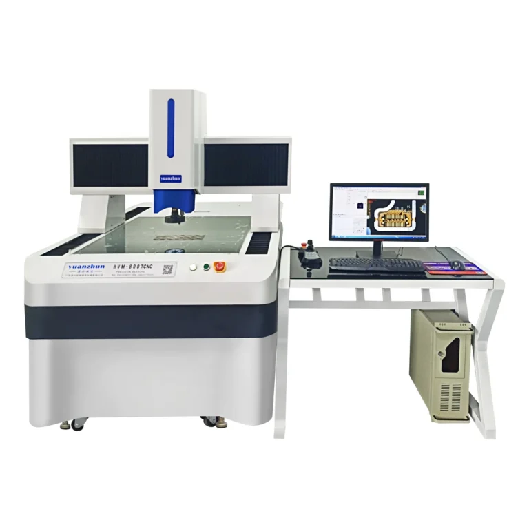
Precision hardware measurement starts with the feature, not the machine. A stamped bracket, turned shaft and machined housing can all be called “precision hardware,” yet their inspection tasks differ. A camera can measure a visible edge without contacting the part; a probe may be needed for an internal or hidden surface. This guide helps you map the drawing to a repeatable inspection method before selecting equipment.
Common parts and what needs to be measured
| Part example | Typical inspection question | Method to evaluate first | What to verify |
|---|---|---|---|
| Stamped bracket or plate | Are the visible profile, hole centers and spacing within tolerance? | 2D vision measurement | Edge contrast, flatness, datum setup and fixture repeatability. |
| Small screw or turned shaft | Can the required side profile or length be viewed consistently? | Side-view optical inspection, if accessible | Orientation, support, surface reflection and whether the drawing also calls for 3D form. |
| Machined housing | What are the positions of accessible bores and surfaces? | Vision for visible features; tactile CMM for appropriate accessible 3D features | Datum strategy, probe or optical access, depth and uncertainty. |
| Cutting tool or tiny feature | Is the edge or profile distinguishable at the required scale? | Measuring microscope or suitable vision system | Magnification, focus, lighting and a validated edge definition. |
These are starting points, not guarantees of suitability. A blind-hole interior, for example, cannot be measured merely because its opening appears in a camera image. The method must reach and resolve the actual characteristic specified on the drawing.
Choose an instrument by access and feature type
Visible X/Y dimensions and profiles
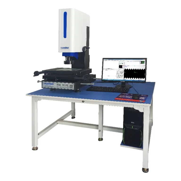
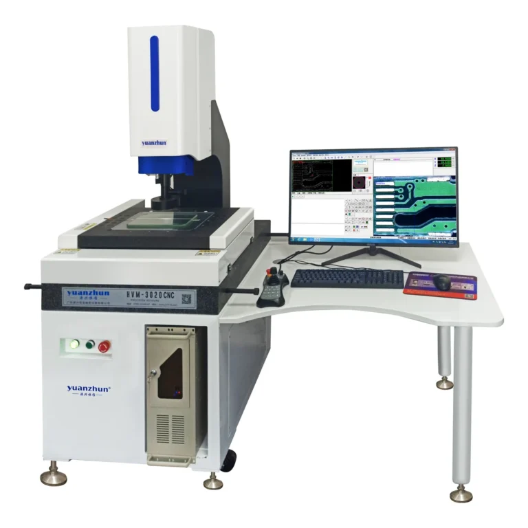
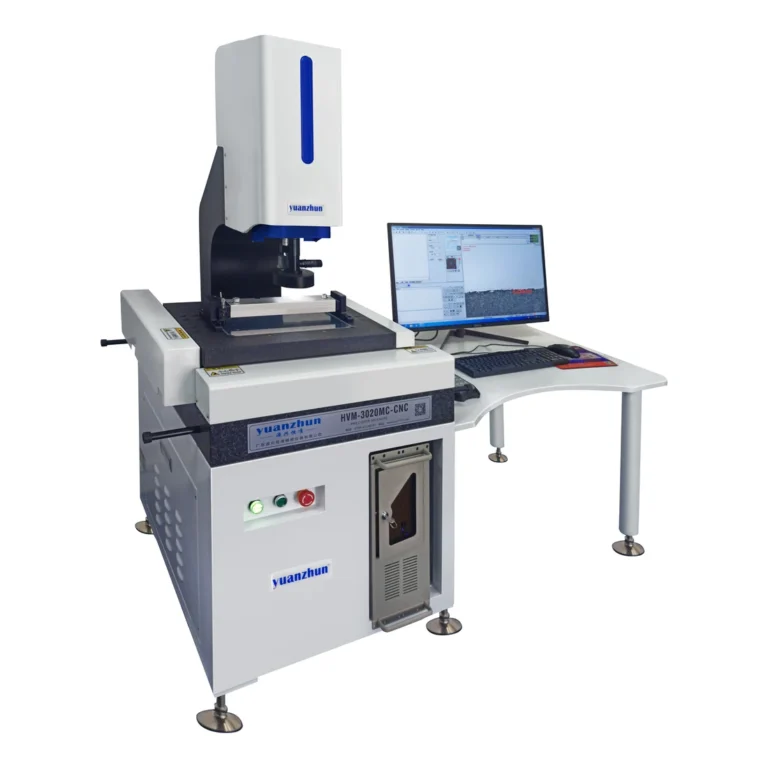
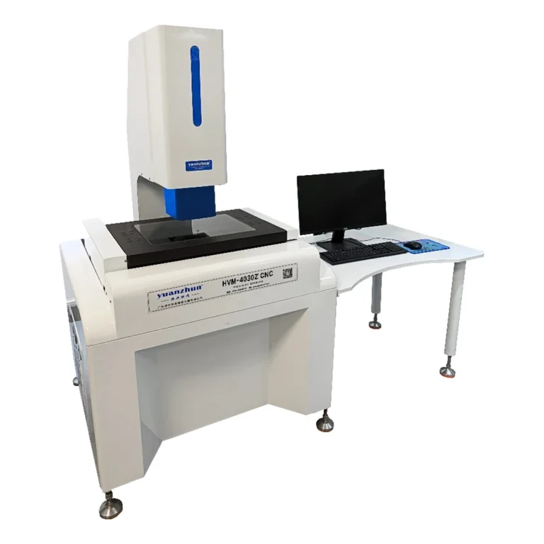
For clear planar edges, a manual 2D video measuring machine can be evaluated for distances, circles, angles and profile-related work. Check the field of view, measuring travel and how the part is aligned. If the same part is inspected frequently, also compare a programmed CNC vision measuring machine using the complete loading-to-reporting cycle, not motion speed alone.
Side features and height-related checks
A side-view arrangement can help when the important feature is difficult to inspect from above. The HVM W horizontal video measuring series is designed for side-view inspection; confirm that its travel, illumination and fixture suit the actual part. For specified height or flatness functions, review the 2D versus 2.5D selection guide rather than assuming every “2.5D” system can measure every depth.
Accessible 3D geometry
Where the drawing requires accessible surfaces, bores, datums or geometry not reliably visible to a camera, evaluate a tactile coordinate measuring machine or another appropriate method. Our vision measuring machine versus CMM guide explains the method-level trade-offs. A probe still needs physical access and a suitable fixture.
Build a repeatable precision hardware inspection plan
- Mark the drawing: list each characteristic, tolerance, datum and required reporting format. Separate visible edges from hidden or 3D features.
- Choose representative samples: include normal parts and examples with realistic finish, burrs, reflections or near-limit dimensions.
- Control the setup: specify orientation, fixture contacts, illumination, focus, magnification and part stabilization.
- Define the measured edge: a burr or chamfer can change which boundary the camera detects; agree on the feature definition before measuring.
- Validate the result: repeat measurements after reloading the part and, where appropriate, compare with a suitable reference method. Evaluate process uncertainty against the tolerance.
- Save the evidence: record the routine, datum, conditions, part ID, operator or program version and results needed by your quality process.
What to send for an application review
Share a drawing or annotated image, part dimensions, material and finish, critical tolerances, sample photos, expected inspection volume and whether results must be exported. If a feature is hidden or the edge definition is uncertain, call that out explicitly. We can then discuss a suitable measurement route and model configuration instead of assuming one machine covers every part.
For the next step, contact Ideal Precision with your part and inspection requirements. If your main challenge is repeat throughput, see the manual-to-CNC measurement planning guide.